Sources to magnetic arc blow
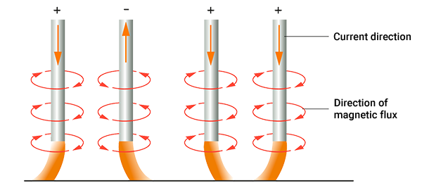
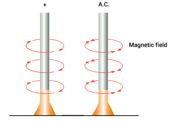
Welding with an electric arc creates a magnetic field around the electrode, according to the illustration below. The intensity of its lines of force, also called the magnetic flux density, gradually lowers as the distance from the electrode increases.
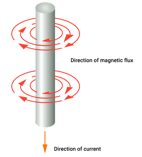
The direction of the magnetic field in relation to the current during welding with D.C.
If the magnetic field is disturbed by external sources, it may cause deflection of the arc during welding. This phenomenon is called magnetic arc blow, or arc blow. It can lead to several kinds of discontinuities in the joint, including lack of root penetration, lack of fusion, undercuts and pores. It may not be possible to eliminate arc blow but steps can be taken in order to reduce its negative effect.
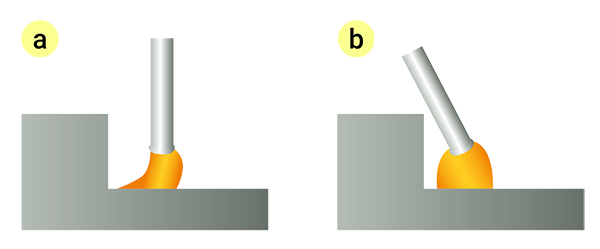
The deflection of the arc can be more or less stable during magnetic arc blow. The source of the interference is what influences its behavior. A deflection of forward arc blow and backward arc blow is illustrated below.
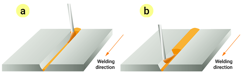
a) Forward arc blow. b) Backward arc blow.
Essential sources that can achieve, or contribute to, magnetic arc blow are:
- Residual magnetism in the steels subjected to welding
- The appearance of the joint
- Welding with multiple electrodes
Residual magnetism is primarily an issue related to tack welds and root runs. After these sequences, the residual magnetism in the joint is normally low enough to reduce arc blow.
Residual magnetism in steels
Ferromagnetic steels, including the Hardox® and Strenx® grades, can contain varying levels of residual magnetism. The magnetic flux density gradually lowers as the distance from the electrode increases. When it is high enough, this magnetism can interfere with the magnetic field from the welding torch and cause magnetic arc blow. Common sources that enhance the magnetism of the steel include:
- Magnets used in jacking equipment
- Storage in a place with high levels of magnetic flux densities.
Low levels of magnetism in the joint will not influence the stability of the arc. Arc blow disturbances can occur when the magnetic flux density is approximately 40 Gauss or above.
The Hardox® and the Strenx® grades are high strength steels with favorable resistance to residual magnetism. However, there are instances when they can obtain magnetic flux densities of 40 Gauss or more. The sensitivity towards magnetic arc blow, caused by residual magnetism in the steel, is generally more emphasized with:
- Hardox® grades of higher hardness
- Higher strength Strenx® grades.
The objective in the following context is to further describe the nature of magnetic arc blow. Suitable remedies are then provided on how to counteract this effect.
Suitable joint geometries
The resistance to magnetic flux depends on the characteristics of the medium through which it flows. Steel has a substantially lower resistance in this respect than air. Consequently, free ends of plates can have a lower level of magnetism than a joint including the same plates.
The level of residual magnetism can vary throughout the joint when the distances between the steels in the joint vary. For instance, in a single-V joint, the distance between the parent metals in the joint are shortest at the root section. Therefore, there is a higher level of magnetism compared to other parts of the joint where the space between the steels is greater, see illustration below.
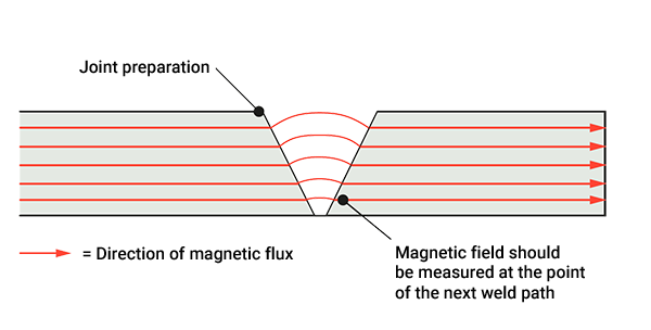
Magnetic fields in a single-V prepared joint.
The magnetic flux density, therefore, should be measured at the location of the next weld pass in order to determine the risk for magnetic arc blow. A hand-held gauss meter is a typical instrument used for this purpose.
The geometry in joints of larger plate thicknesses can cause an increased risk for magnetic arc blow. Welding in this condition means that a substantial fraction of the arc can be surrounded by the parent metals at a close vicinity. It can especially occur during root passes and tack welds.
Since the magnetic field flows easier through steel than air, an unsymmetrical magnetic field can be formed around the torch. This effect may cause arc blow.
Similarly, arc blow can occur when welding plates of different thicknesses, according to the illustration below. In this situation, the arc may deflect towards the thicker plate in the joint.
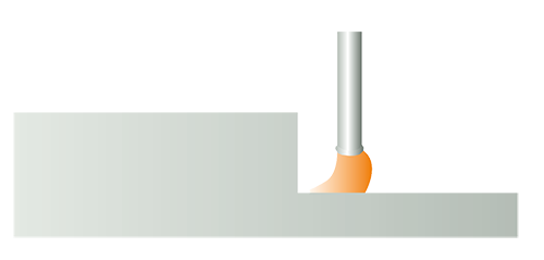
Arc blow due to different plate thicknesses in the joint.
Welding with multiple arcs
Multiple electrodes normally lead to increased welding productivity in comparison to welding with a single electrode. Welding with multiple arcs using D.C., where there is only a small distance between the electrodes, may cause arc blow. This since the magnetic field from each electrode can influence the performance of the adjacent arc.
If arc blow is encountered, equal polarity between the electrodes supports inward arc deflection and unequal polarity supports outward arc deflection, according to the illustration below.
Arc deflections during welding with two electrodes.
Measures to counteract magnetic arc blow
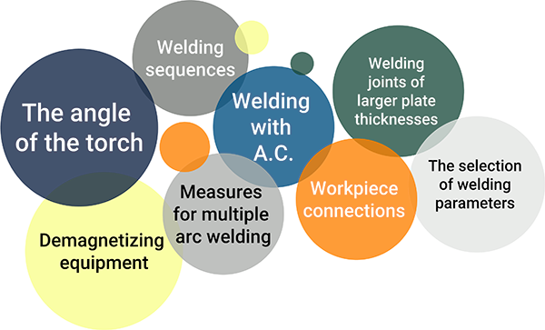
The angle of the torch
Welding sequences
Tack welds and root runs diminish and/or redistribute the magnetic fields in the joint.
This effect is brought on by:
- Heating of the joint due to welding.
- A redistribution of the magnetic field. This is facilitated if weld metal is present in the joint. It can then acts as a bridge for the magnetic flux flow.
The following two steps can be utilized to plan the welding sequences appropriately so that the level of magnetism is below 40 Gauss in sections of the joint: First, mark the locations in the joint where the local magnetism is below 40 Gauss. Then place tack welds at suitable locations along the marked areas. Long individual lengths of tack welds are preferred. Their individual lengths should generally be set to a minimum of 50 mm each. Welding of joints with a plate thickness up to 8 mm may be done with shorter tack lengths than 50 mm. Repeat this procedure until the magnetism is below 40 Gauss in the complete joint. Then the rest of the welding procedures can be performed.
Welding with A.C.
Electrodes connected to A.C. are less prone to arc blow in the joint compared to those coupled with D.C.
The reasons are that:
- The direction of the magnetic field around the electrode continuously changes making it less susceptible to external sources of magnetism.
- Welding with A.C. introduces eddy currents into the joint, see fig…, which reduces the negative effect from an external magnetic field.
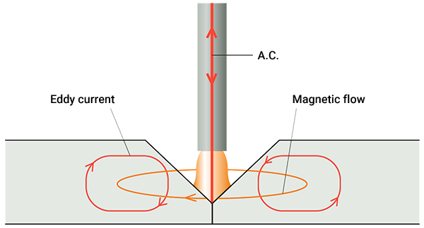
Induction of eddy currents in the joint.
Workpiece connections
Proper placement of the workpiece connection can diminish magnetic arc blow. This technique introduces a magnetic field in the opposite direction to the one causing the arc blow.
The cause is that the current return from welding goes through the workpiece. It thereby causes a magnetic field in its path. This magnetic field supports an arc deflection away from the workpiece connection, according to the illustration below.

The position of the workpiece connection supports an arc deflection in accordance with the illustration.
If back blow of the arc is encountered, it can be counteracted by positioning the workpiece connection away from the direction of welding. If forward arc blow occurs, locate the workpiece connection towards the direction of welding.
The use of more than one workpiece connection might further improve this method.
The effect from the location of the workpiece connection is limited. Consequently, this measure is normally done together with other complimentary measures in order to avoid arc blow.
Welding joints of larger plate thicknesses
Demagnetizing equipment
The selection of welding parameters
The stability of the arc depends on the welding parameters. A short arc length and low current value can stabilize the arc. If needed, a reduced diameter of the consumable further assists in reducing the current level. However, observe that a lowered current level promotes lowered welding productivity.
The selection of welding parameters
Arc blow encountered when using multiple electrodes can be counteracted by feeding one or more electrodes with A.C. In this case, the electrode with A.C. continuously changes the direction of its magnetic field. This measure counteract arc blow, according to the illustration below.
Welding performances with two electrodes using a 0combination of D.C. and A.C.
A beneficial technique to use during multiple arc welding is to combine the positive aspects from both A.C. and D.C. welding. The first electrode is fed by a D.C. current with positive polarity in order to attain a deeper penetration profile. The other electrode/electrodes are supported by A.C. When applying two electrodes connected to A.C., the current phase shift between them can be set to approximately 90° for a high resistance to arc blow.
The information in this report is only applicable to SSAB’s products and should not be applied to any other products than original SSAB products.
This report provides general results and recommendations for SSAB steel products. This report is subject to SSAB’s Terms of Use. It shall be the user's responsibility to verify that the information contained herein is correct and is suitable to be used for the particular purpose and application of the user. The report is intended to be used by professional users only who possess adequate expertise, qualification and knowledge for the safe and correct use of the results and recommendations in this report. This report is provided “as is”. The use of the report is at user’s own discretion and risk and that users will be solely responsible for any use of this report. SSAB disclaims any liability for the content or potential errors of this report, including but not limited to warranties and condition of merchantability or fitness for a particular purpose or suitability for individual applications. SSAB shall not be liable for any kind of direct or indirect damages and/or costs related to or arising therefrom, whether special, incidental, consequential or directly or indirectly related to the use of, or the inability to use, the report or the content, information or results included therein.